Batch 15 – Finished.

First off – A HUGE apology. I did say that I was going to document all of the steps in this build which I did up until the half way point. But then life got in the way and I found the writing slipping behind the production and before I knew it there was hours of work needed to catch up with the photography editing and writing and it slipped down the priority slippery slope. Apart from being a bit more CNC driven, all of the steps were similar to the processes I have already detailed during previous builds. If there is anything you really need explaining, send me a message and I’ll swamp you with so much detail you will wish you never asked.

So, I ended up with 3 jumbo baritone ukes and a jumbo ubass. The ubass is a lot of fun with those big fat bass notes. It is strung with Aquila thunderbrown strings which to me sound fabulous but I dont have a lot to compare it to as this is the first ubass I have built. I was concerned about how the JJB twin piezos would work with the string tension and low frequencies but there is plenty of gain and it sounds good even through my Vox guitar amp. The headstock might be one of those love it or hate it things. I wanted to keep the weight down and avoid that huge wingnut look. It goes off to its new owner this weekend who I hope will be happy with the result. The baritones have plenty of volume and a deep rich tone from the mahogany. I have tuned them to Bari pitch but I expect their new owners will try and tune them up to regular low G tuning and I’m not sure the worth brown “strong” strings will take it. Time will tell.

One of the Baritone ukes is destined to be the prize at the charity raffle at the Mandurah Uke Fesival in April in support of Mums Cottage. The tickets aren’t available yet and I dont know if they will be available for presale or remote sale but I might link to it when the committee get that bit of the festival organised.

And that is about it for a while. I’ve made about 65 instruments over 13 years and have decided to take a step back to refresh my batteries. I’m thinking of dipping my toe into silversmithing and particularly lost wax casting of jewellery. Something new and fresh to learn. I expect I will come back to uke making but it might be a couple of years before I start working with wood in this way again.

I’ll still be monitoring this site so if you have any questions please get in touch.

Cheers

Paul

15.11 Closing the Soundbox

It is a nice milestone to close up the soundbox as it is about the half way point in the build. Its not a quick step, as the notching out of the braces to fit the plate braces seems to drag on but it needs to be done right and that takes a while. I glue on the back plate first, trim off the small overhang and then repeat the steps to attach the soundboard.

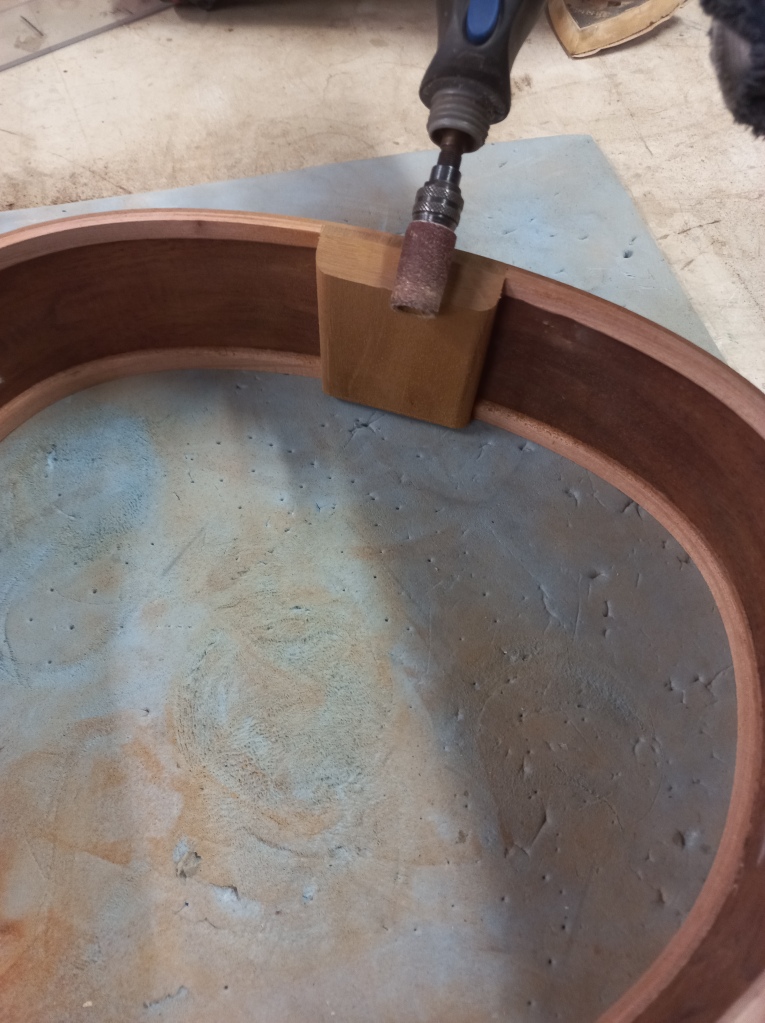
The first thing is to mount the sides in a mold and using cawls and screw jacks encourage it to take up the perfect shape. There isnt much force involved as the sides conform to the mold very well. If you look closely at the second picture where the back plate is leaning up at the back you might be able to see very small triangle notches at either end. These are exactly on the centre line and they mate with the sort of arrow head blocks that are screwed to the mold. This combination lets me remove and refit the plate over the sides in exactly the same position as I cut the notches into the linings where the braces engage. The notches are cut with a dremel and chisels and its a fiddly little process of trial and error to get them right.

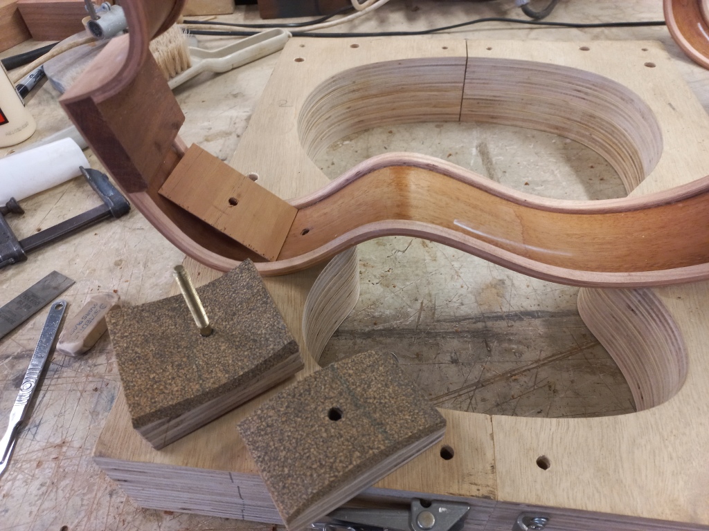
On previous builds I made a full set of the little clamp buttons that can be seen in picture 2 on either side of the arrow head blocks to go all the way around the perimeter. These pull the plates down evenly onto the strange geometry that is the glue edge of the sides. I even installed the thread inserts in the mold to do it that way this time then thought I would do it a bit differently this time and use the gobar deck to snug the plate down while the glue dries. I cut a piece of lino which sits on top of the plate to stop the spring ends from digging into the mahogany. After the titebond glue had dried the screw jacks and cawls were removed and the half closed up soundbox is pushed out of the mold. Using double sided tape I attached cork levelling strips to either end of the back plate. The back of the instrument has a taper from end to end which means that if it is used as the plane that supports the instrument while the router removes the overhang the sides are not perpendicular to the back plate. This can result in the router removing a chamfer rather than just the overhang and by levelling the back plate this is avoided.

It is then time to close the box by attaching the soundboard. I again need to encourage the sides to snugly conform to the mold so I use the cawls and jacks. This time, all of those parts will need to be removed from the box through the soundhole. I’m told it is very embarrassing to realise that the cawls are too big for the soundhole and so far have been very lucky to avoid that trap. You will see that I have a length of wire wrapped around the back jack and by pulling this I can collapse the jack for removal if I cant get my hand through the soundhole to get access to it. Neat trick, kind of like the boat in a bottle. The soundboard was snugged down using the gobar deck, the cawls were removed and the closed box pressed from the mold. The overhang was cut away at the bandsaw and the router table and the step was complete. Now just to repeat it three more times.

Cheers

Paul

Batch15.10 Soundboard Bracing

Howdee,

Before the soundboard bracing can be glued in place the bridge plate needed to be glued down. I use 0.5mm carbon fibre sheet for this and cut out the pieces (which are 5mm bigger all around than the footprint of the bridges I will be making) on the cnc router. The bridge plates are attached to the soundboard with epoxy and are held in place for gluing with the 25′ side of my radius dish and gobar deck. I also glue the Jarrahdale String Instrument Company label into the back plates. Another couple of little prep jobs was to drill the pickup jack holes through the end blocks and to bevel the edges of the end blocks.

As detailed in post 15.7 (back bracing) I make a laminated bracing product from carbon fibre sheet and spruce. That post also shows how I cut out the braces with the radius dish curves built in using a cnc router. I usually use a double X bracing pattern as it has helped produce the bright sound I strive for in my instruments, time will tell how it goes with the strong bass notes I am hoping to get out of these instruments. So with the braces already mad,e all I needed to do was cut the two halving joints in each brace so they could fit together in a double X and I do this on the cnc router. The braces are then assembled with a spot of glue in the halving joints. I reduce the spruce top edges of the brace assembly to remove unnecessary material using a sanding block. Cutting out the braces with the 25’ radius already on the glue edge removes the need to manually radius the finished double X which would have previously been the next step prior to cnc. The last little job is to remove the little area on the back of the braces which sit atop of the bridge plate. It is only 0.5mm but interferes with the glue joint. I mark up where the material needs removing and then route away the interference. The double X brace is finally glued into the soundboard using my 25′ radius dish and go bar deck. And last of all, the flat bottomed transverse braces in front of the soundholes are glued on and the plates are complete – and the sound boxes are ready to be closed up which will be the subject of my next post.

Paul

Batch15.9 Fitting the Rosettes

Howdee,

A quick little post about using the cnc router to cut the circular rebate and fitting the rosette, making and fitting the reinforcing ring and cutting the soundhole. I dealt with making the rosette in the previous post and the soundboards in post 15.6. While cutting out the soundboards I drilled a 6mm pilot hole in the centre of the soundhole and will be using this to locate the soundboards on the cnc router table. I start by using the cnc to drill a 6mm hole in its waste board. After zeroing the cnc to this position I fit a dowel into this hole and use it to locate the soundboard under the cutter. I check the finished size of the rosette with a digital caliper and generate the toolpath to cut the rebate. The rosettes are then glued into the rebate with titebond. Once the glue is dry the rosette is levelled and the soundboard is thicknessed to 2mm by sanding away the back.

I like to glue a 1mm thick disk inside the soundboard to reinforce the soundhole and make this from the same timber as the soundboard. Its a simple job on the cnc to make these disks with a 6mm centre pilot hole. Then using the existing pilot in the soundboard it is easy to locate the reinforcing disc for gluing.

The soundboard is now refitted to the cnc table over the locating dowel to cut out the soundhole which on these instruments are 82mm in diameter.

I then blend in the perimeter of reinforcing with a ROS and the soundboards are ready for bracing.

Paul

Batch15.8 Rosette

Howdee,

On all of the instruments that I have made, the rosettes have been round with a combination of wood and shell / recon stone for bling. CNC opens up a lot of opportunities for different shapes but for these instruments I have continued with round. I have detailed in previous builds how I use a router trammel to make all of the circular parts but this is the first time I have done it with a CNC router and I was amazed how perfect and chip free all of the parts came out especially when using a downcut spiral cutter.

My previous rosettes which used recon stone for the bling ring were all small enough that I could make a four sided square frame to cut the ring out of the small blocks of stone I could purchase. I found a supplier of larger slabs of stone for these larger rosettes but to reduce waste decided to cut 8 tiles to make the an octagonal frame. I started by cutting the recon stone into 2mm thick sheets on a diamond wet saw. I levelled up the thickness on a sanding thicknessor and then glued the sheets to scrap ply using epoxy. A little bit of designing in the CAD software and the toolpath was ready for cutting out the little tiles with the correct angles to glue together into an octagon. Really easy and after 10 minutes on the cnc router the tiles were all cut out. I then cut off most of the chipboard backing on the bandsaw and then wasted away the rest on the sanding thicknessor after fixing the tiles to a sled with double sided tape. I assembled the eight tiles into an octagon with super glue and then glued the octagon onto scrap chipboard with epoxy. This was then put back under the CNC router which made easy work of cutting out the rings. Then same as above, waste the chipboard and then remove the residual glue on the sanding thicknessor.

The timber ring is black mulga which is also what I intend to use for the headstock veneer. I break down a block on the bandsaw and then thickness the slices on the sanding thicknessor. As the timber had a few cracks and holes I made a perspex template of the rosette on the cnc which allowed me to see and mark the best centre to avoid the imperfections. I then cut out the disks on the bandsaw and glued the disks into more waste chipboard with epoxy. Again, a bit of designing in the CAD software and a toolpath was produced to cut the timber ring with the rebate for the stone ring. After the cnc routing, the stone ring was then get glued in with superglue. I cut away most of the chipboard but left 5mm on the backs of the mulga rings for support.

I like to add a 0.5mm black shadow line around the inside and outside of the rosette as it highlights the colour contrast. I use black dyed timber veneer for this and have found that the best way to hold the veneer strip while the glue dries that secures it to the mulga ring is to make an internal and external plastic form. Previously I would have made these on a metal work lathe but I knocked these ones up on the cnc router from blocks of polyethylene. The residual chipboard is then removed on the sanding thicknessor and then a final pass on the show side to clean off any remnant glue and the rosettes are finished at 1.7mm thick.

cheers

Paul

Batch15.7 Back Braces

Howdee,

I make laminated spruce and carbon fibre braces as they allow me to reduce the physical size and weight of the braces while maintaining their stiffness. I used braces that were 3.5 wide by 6mm tall for all of my previous ukes but am scaling it up this time to allow for the considerably greater soundboard surface area and string tension of this batch. For the ubass, jumbo bari and the tenor guitar the soundboard braces will be 6 x 8 which compares to 6 x 12 for a genuine Kala ubass. The bouzouki guitar will be 6 x 10 as it has 8 strings. All back braces are 6 x 10 and are made with 1mm premade carbon fibre woven sheet attached to the spruce outer layers with epoxy. The sheet of laminate is 140mm x 310mm and where as I would have previously cut the sheet up into strips and then route on the end profiles and sanded on the radius, this time I made them with the cnc router.

I’m really liking this cnc machining and this is a typical production step which was previously tedious which is now quicker and more accurate.

Before I can glued on the back panel braces I needed to glue on the back spline over the centre joint. To hold it in place while the glue dries I used the radius dish and gobar deck. I notched the radius face of the braces to sit over the back spline also on the cnc router. I then glued the braces in place with titebond original using the go bar deck.

The ubass will have those huge floppy rubber strings and although it will have a through bridge, it needs a special access panel in the back plate to get access to the back of the bridge to install the strings. At least this is how Kala do it and I’m following their lead. I intend to attach the access panel with little screws but want the screws to engage into metal rather than wood so I made a brass backing plate and epoxied to the inside of the back plate and between the braces. I will drill and tap the brass plate for M3 screws to secure the access panel. It came out nice and tidy and the gloss black access panel looks smart.

Cheers

Paul

Batch15.6 Plates

Howdee,

Plates is the collective term for the flat panels that are the soundboard and back panel. Each plate is a bookmatched pair of boards and I have previously detailed how I go getting a perfect joint between those panels prior to gluing them together. But this whole build is about maximising the use of my new cnc routers and I thought there might be an opportunity to get them to cut this joint.

In a previous post I showed how I cut the panels on a bandsaw and thicknessed them on a sanding thicknessor. They have been hanging in my humidity controlled room for a few weeks ready for the jointing operation.

I decided that it would work well to cut both halves of the joint in one pass so I clamped a piece of sacrificial chipboard to the table and manually controlled the spindle with a 6mm bit to cut a straight groove it across it. I then clamped both halves of the plate over the groove and using a manual cnc mode called MDI ran the cutter between the boards at a slow feed rate of 500mm/min. Absolutely perfect!

I then glued the halves together with red cap titebond pulling the joint tight with masking tape. At the end of this step I had eight plates and separated out the best four to become soundboards and the rest to become back panels. Using fusion360 designed the cutting operation to cut out the semi finished plate shapes. I say semi finished because I make them 3mm oversize with the intention of trimming off this overhang after they are glued to the sides. One of the big benefits of CAD/CAM (computer aided design/computer aided manufacture) is that once you have a design in the software, manipulation or copying of that design is easy. So all of those body molds, fox bender molds and cutaway molds were based on a copy of the original template which is very easy to do. So designing something to cut out the plates at 3mm bigger than the template was very straight forward. I used a 2mm downcut bit to cut out the plates and completed all eight in about 45 minutes. I even put a 6mm centre hole as a pilot for the soundhole in the soundboards. Exactly on the spot every time.

There was also a last little job to finish the preparation of the sides for the plates to be glued on. I like to put side soundports on my instruments and glue in a little 1mm counter veneer to strengthen the area against the risk of a crack developing from the soundport. The manufacture of the little clamping cawls was another cnc project which was based on the curves of the original template.

Cheers

Paul
Batch 15.5 Linings

Howdee,

Linings are a reinforcing strip that helps strengthen the joint between the soundboard and sides and the back panel and the sides. They are normally made from a kerfed softwood which is easily bent around the curve and glued into the sides before the plates are attached. Never one for the easy option, I make a solid wood lining which and this weeks post will detail how I install them. Making the solid lining is a lot more work but I’m convinced by the acoustic theory that says that soundboard vibrations are lost into the sides through soft kerfed lining but are retained by the hard rim of a solid lining. All of this acoustic theory stuff is difficult to prove but this idea seems to make sense to me.

I covered the making of the lining out of four 1mm laminations in post 15.3 – bending. The last post (15.4 cutaway) ended with the end blocks and cutaway having been fitted.
The next build step is to level the face that will eventually have the soundboard attached. I want the plane of this surface to be perpendicular to the sides so I secure the sides into a body mold with spreader blocks and screw jacks and remove any end block overhang or side misshape on a MDF board with 100 grit abrasive glued to it. The solid lining are then trimmed to fit and glued in with titebond and held in place with pegs. After the glue has dried, the edge is again flattened on the abrasive board.

The plane of the back panel slopes towards the neck heel and is slightly domed so there is some weird geometry going on and the back linings need to be installed to support this complicated shape. I decided to make the sides 73mm deep at the heel block and 66mm deep at the heel. I marked up these dimensions onto the ends and use the edge of a thin sheet of plastic as a flexible straight edge to join these depths with a pencil line around the sides. While mindful that the dome (which is a 15 foot radius) of the finished body means that it isnt a straight line between the end block and the heel I remove the waste while leaving a generous margin in a linisher. The edges are then sanded to the 15 foot curve on a thing called a radius dish, (the shape of which is called a conical cap) which is covered in 100 grit abrasive. The sides are supported in the body mold with spreader bars and screw jack and the edges are abraded until the 73 and 66mm dimensions are established. The white chalk helps me see that all of the edge has been levelled. With the sides of one body radiused, I copy the line between the end and the neck blocks into a sheet of plastic and this becomes my markout template for the other 3 bodies. This more accurate cut line allows me to trim the waste away closer to the finished shape with more confidence. With the taper and radius established the body is refitted into the body mold and the linings are glued in place as per the sound board step. And then, after the glue has dried the back panel edge and linings are cleaned up on the radius edge. The sides now feel really stiff which you dont get if kerfed linings are fitted.

Cheers

Paul

Batch15.4 Cutaway

Howdee,

My last post included a few pictures of the mini fox bender that I made to bend the side piece that is the flo cutaway. This post will look at how I deal with the fiddly little joints that connect this little curve with the rest of the sides.

But first I needed to trim the sides at the end joint and glue in the end block. The reason I join my body molds together with a hinge is to make this little job a bit easier. I start by removing the hinge and adjusting the position of the bent side in the half body mold so that it is central and so the waste bend sits in the correct spot. The cross clamps work well at securing everything when I get it in the correct place. I then bandsaw off the waste and trim up the end grain with a plane and sanding block. Repeat for the other half and then reassemble the halves of the body molds with the hinge. A small sheet of stainless shim slipped between the sides and the end mold is there to make sure the glue joint is exactly level and to stop any glue squeeze out sticking the sides to the mold when the end block is glued in place. I made the curved face on the end block on my CNC router to 305mm radius.

The side assembly is then removed from the body mold and the area that will become the cutaway is removed on the bandsaw. With the excess neck joint/cutaway material removed the sides now fit into the cutaway mold properly and are aligned and secured with a few clamps. I trim the faces that will be the cutaway glue joint with a sanding stick the rubs against posts which are attached to the cutaway mold. These 40mm posts have an eccentric hole through which a screw secures them to the base board. By swinging the posts on their eccentric mounting screws I can fine tune the angle of the little facet that will become the glue joint.

I use the same eccentric post idea on another jig that helps me trim the length of the cutaway curve. A bit of trial and error on the first cutaway and then the position of the sanding posts is set for the other three bodies.

I glue the cutaway curve in place with the sides still in the mold and rely on its slight springiness to hold it in place. I then glue in the neck block and a little molding into the horn of the cutaway to reinforce the joints.

Cheers

Paul

Batch15.3 Bending

Howdee,

I have previously detailed how I go about side bending but here it is again. The technique I use is called Fox Bending and involves heating the 2mm thick timber using an electric blanket and forcing it along with some steel strips around a mold. I use this approach because it allows me to bend highly figured, fragile and expensive timber into tight curves with confidence that it wont crack. The sequence of steps that I use are:

  • Soak the timber for a few hours in water.
  • Wrap the timber in an oven roasting bag. This slows the rapid evaporation of the water within the timber as it is heated. At high temperatures and in the absence of moisture the timber is brittle but there is a sweet short period where the wood is above 100degC but all of the moisture hasn’t escaped and that is when the timber is pliable.
  • Assemble the bending sandwich of stainless steels shim, heating blankets and timber in the fox bender with the spring loaded rollers and screw presses in place.
  • Start the temperature controller that regulates the blanket temperature to 130degC.
  • When the temperature gets to 105degC ( which takes about 30sec) wind down the waist press, roll around the front bout roller, roll around the back bout roller ( this is all done in about 30 seconds), secure the rollers and set the temperature controller to keep the temperature at 130degC for 30 minutes.
  • Let the assembly cool down for a few hours.
  • Restart the temperature controller at 130degC for another burst of 30 minutes.
  • Let the assembly cool down and dismantle.

I have worked this sequence out by trail and error (lots of error!) but I’m now at a place where I cant remember the last time I cracked a side. Double heating blankets and all of the shim backing strips is probably overkill for plain simple mahogany but when I’m on a roll I’ll stick with the system.

These instruments are going to have florentine cutaways so I also made a mini fox bender to bend those little curved bits.

Linings are the bendy strips that are glued inside the soundbox to reinforce the joint between the sides and the plates (soundboard and back panel). This is usually a soft kerfed strip but I like the theory that a solid rim adds to the acoustic properties of the sound board. Instead of the soft and light kerf lining I make a 4mm thick ply lamination out of 1mm thick strips of hardwood (here acacia). I glue the four strips together between a positive and negative mold and then break the 80mm wide lamination into 10mm wide linings. These end up very stiff and the thinking is that they resist vibration loss into the sides.