Hi
I thought I’d post an update on the progress of this batch of pear shaped tenors. The tasks have been a bit fiddly so progress has been slow but steady. I used a foxbender to bend the sides which went well after lots of practicing on scrap jarrah. I forgot to take any pictures of the bending of these sides but there is a separate tutorial on foxbending here. I attached the end blocks (tutorial here) to the sides and then tapered the nd profiled the hollow body on the radius dish. I then glued the centre spline and braces to the back panel using the go bar deck then glued the back panel to the sides.
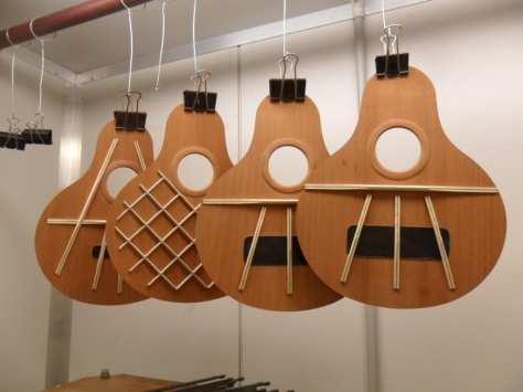
I inlayed the rosettes (which were the subject of a previous post) into the soundboards and then set about designing the bracing patterns for the fixed bridge design and floating bridge design. As explained previously I’m making four ukes in this batch and two will be identical fixed bridge instruments and two will be floating bridge instruments. Before I could work out the details of the bracing I had to committing to a scale length because the bridge location sets the bridge patch location and the bridge location is part of the scale length. I wanted 14 frets to the body but that would have set a scale length of close to 20” to put the bridge just where I wanted it. Even 13 frets gave a scale length of 19”. I finally settled on 12 frets to the body and a scale length of 18”. The narrow body width at the neck joint is almost like a cutaway so accessing the frets over the soundboard shouldn’t be too hard.
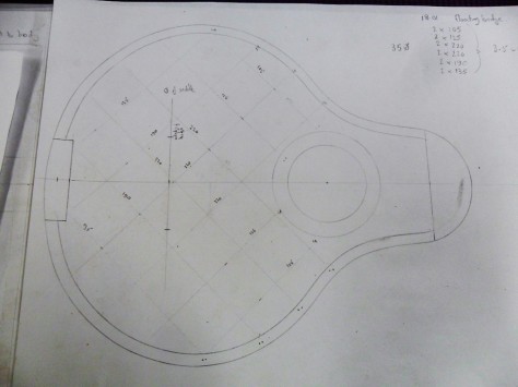
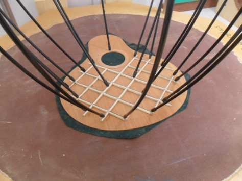
Of the floating bridge ukes, one will have modified fan bracing and one will have lattice bracing while the fixed bridge ukes will have conventional fan bracing. I made some full scale drawings of the soundboards and sketched up some bracing patterns that looked about right and this is where the pictures below pick up the story. This level of design is new to me so the number, length and position of the bracings bars and tone bars was a bit of a guess based on google image search but I settled on a basic fan brace configuration. My research into flat top floating bridge instruments suggests there is a stress area around the sound hole so I extended the fan braces up either side of the soundhole for this instrument. The braces and tone bars for the fan braced instruments are 6mm wide by 8mm tall with 0.5mm carbon fibre laminated on edge down the centre of each brace and tone bar. More information about some interesting tests I did on brace mass reduction with CF reinforcement is here. CF destroys chisels but doesn’t seem to bother tungsten carbide so I did all of the brace shaping at the router table prior to gluing them in place. All gluing was done on the radius dish after the bottom of the braces had been sanded also on the radius dish to a curve to match the desired sound board radius. I am using a 25’ radius on the fixed bridge instruments and a 15’ radius on the float bridge instrument sound boards.
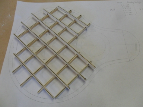
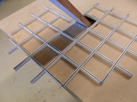
Making the lattice bracing was a fun exercise. Well it was fun for me because I enjoy the creativity and problem solving that I put into jig making. I cut the halving joints for the lattice using a sliding table that I made for my bench top router. The little indexing pin thing worked really well for getting the lattice spacing exactly correct. The individual bars of the lattice were 3.5mm wide by 6 mm tall. I relieved the top edges of the lattice segments with a sanding stick to tidy it up and reduce the mass before radiusing the whole glue down side of lattice to 15’on the radius dish.
You will notice that I use a 1mm carbon fibre bridge patch on the fixed bridge instruments. I decided to use a small one on the fan braced floating bridge uke as well to spread the bridge footprint a bit. I attached the bridge plates to the underside of the soundboards with epoxy but used titebond original for the braces and tone bars. The titebond wouldn’t secure the braces to the bridge plate where they overlap because the CF isn’t porous so to avoid any future problems with the two touching surfaces chattering I relieved the contact area and left about a 1mm gap.
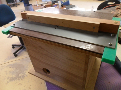
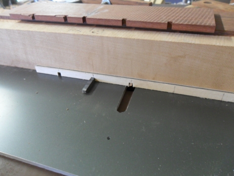
I thought I’d have a go at making side sound port on these uke and decided an oval hole would look good. I attached a 1mm cross grain patch on the inside to reinforce the hole. I then attached the soundboards to the bodies using the method detailed here. A bit of trouble to set up for but it is by far the best way I have seen. All of the spreader bars and screw jacks force the sides exactly into shape while the soundboard is glued down. It can be a bit fiddly after the glue dries getting all of the bits and pieces out through the small sound hole but it makes a very accurate sound box shape. It was then just a matter of routing off the soundboard over hang at the router table. I then made a thin nd flexible oval perspex template and using a scalpel scribed the sound port shape onto the uke side. I removed most of the hole with a drill bit and then carefully removed back the rest of the waste back to the line with a sanding drum in a dremel.
And that was the soundboxes finished. Well not quite, the binding needs fitting but that will probably be the subject of my next post. Upsizing the body has meant that a lot of the jigs that I made for the soprano’s are too small or short for the tenors so I’m having to reproduce them in a larger size and this is the case with the tortoise shell edging jig.


You must be logged in to post a comment.